|
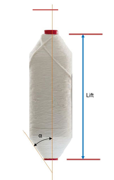
Builder motion is used to wind the roving in a parallel wound package with conical ends as shown in Figure 1. The package is formed layer by layer. The lift of each layer is shortened by a small length which decides the taper angle ‘α’.The animation A1 demonstrates the basics of formation of the roving package. |
Click on Image to run the animation |
|
Figure 1. Roving package Animation A1 Roving package formation |
|
The rovings are wound in coils around the bare bobbin to start with. The winding of coils starts from the bottom position determind by the position of the bobbin rail. As the bobbin rail moves up the coils are wound upwards forming the first layer of rovings on the bare bobbin. After reaching the top position of the lift for the first layer, the bobbin rail reverses the direction of movement and starts to move downwards. Now the coils are placed downwards and second layer of roving are wound on the first layer of rovings. This time the bobbin rail does not go all the way to the starting point of the first layer. Instead, it returns and start to move upwards from a level just above the starting level of the first layer, the difference in these levels is called as ‘shift’ (S). The third layer of roving is wound over the second layer of rovings upwards. Again the bobbin rail does move all the way up to the starting level of the second layer but returns from a level just lower by ‘S’ and starts forming the fourth layer. The distance ‘S’ decide the taper angle. Higher is S, smaller will be α. |
| The roving can be wound onto the bobbin using either Flyer lead method or Bobbin lead method. |
Flyer Lead |
- Flyer surface speed is faster
- Flyer winds the roving on the bobbins surface
|
Bobbins Lead |
- Bobbins surface speed is faster
- Bobbins winds the roving onto itself
|
| Advantages of Bobbins Lead |
- In case of roving break, the direction of roving on the bobbins provides stable outer layer
- The drive to the spindle is shortest hence it starts faster than the bobbins.
- This leads to more roving breaks in flyer lead while staring.
|
|
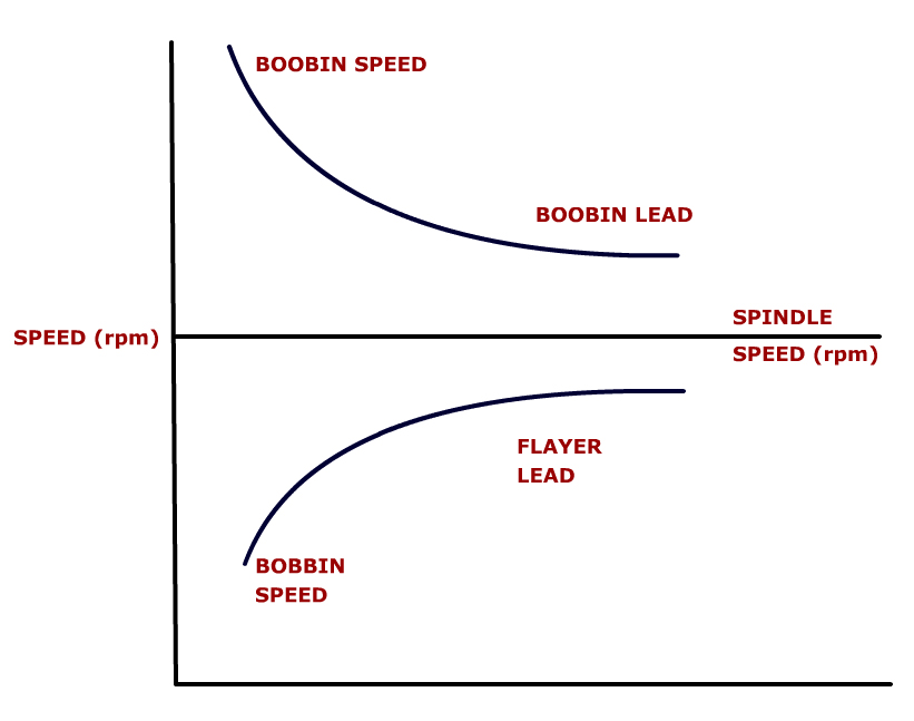
Figure 2 : Spindle speed and Bobbin speed for different Winding methods
|
|
In both the cases, the spindle speed remains constant through out the winding process, since changing the spindle speed will change the twist density in the roving. The bobbin speed is changed according to the requirement. Figure 2 shows the manner in which the bobbin speed has to be changed in case of bobbin lead and flyer lead methods.
|
In both the cases, the roving delivery speed is constant decided by the surface speed of the front pair of drafting rollers. But, as the bobbin builds up the diameter and the circumference of the bobbin increases. If the bobbin rotates at a fixed speed, then the roving will get stretched more and more in case of bobbin lead method since the bobbin is leading and winding the roving on to itself as the winding proceeds; the roving will get slackened more and more in case of flyer lead method as in this case the flyer is leading and winding the roving onto the bobbin. The difference between the peripherals speeds of the flyer and the bobbins needs to be kept constant for proper winding. |
Hence, in case of bobbin lead method the bobbin speed has to be gradually decreased and in the case of flyer lead the bobbin speed has to be gradually increased in order to keep the roving tension constant while winding the rovings on the bobbin. |
For cotton system, because of the advantages of bobbin lead method and the difficulties associated with flyer lead method, the bobbin lead method is always used. |
| Flyer Lead |
- Flyer surface speed is faster
- Flyer winds the roving on the bobbins surface
|
| Bobbins Lead |
- Bobbins surface speed is faster
- Bobbins winds the roving onto itself
|
REQUIREMENTS FOR BOBBIN BUILDING :
|
Based on the above discussions, in order to have proper winding of the rovings on the bobbins, the following requirements should be met: |
 |
The rotational rate of the bobbin should be reduced for layer formation |
|
Shorten the lift after each layer to form tapered ends on the bobbin |
|
Reverse the direction of movement of the bobbin rail after each layer formation |
|
The speed of the movement of the bobbin rail should be reduced after formation of every layer, as it will take more time to lay one coil as the bobbin builds up. |
|
Drive system in Roviing Frame : |
|
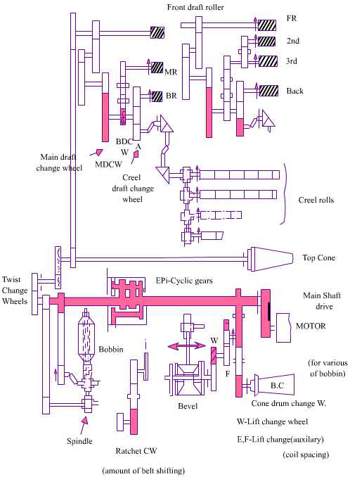
Figure 3 : Typical drive system in a roving frame |
|
The main shaft received the drive from the motor and rotates at a constant speed. It provides the constant drive to the differential gear assembly, top cone, drafting system and the spindle as shown in Figure 3. The bobbin rails gets it motion directly from the bottom cone drum. The bobbins get their drive from the output of the differential drive which combines the fixed speed from the main shaft and the variable speed from the bottom cone drum. The operating principles of cone drums and the differential drive are explained below. |
Cone drive transmission : |
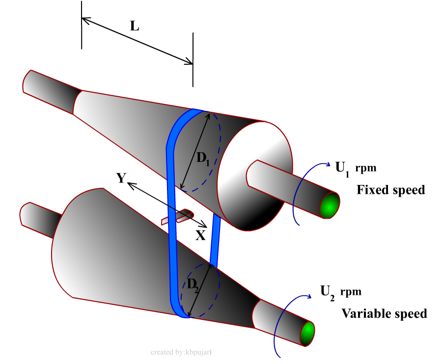
The reduction in the rotational rate of the bobbin and the reduction in the speed of movement of bobbin rail are obtained with a cone drive mechanism. In this mechanism, shown in Figure 4 there are two cone drums out of which the top cone drum receive a constant rate of rotation from the motor. Depending up on the position of the drive belt between them, the speed of the bottom cone drum changes. Hence, at any given position of the belt the sum of diameter of the top cone drum (d1) and diameter of the bottom cone drum (d2) should be a constant. |
Cone Profile |
 |
- Variation in bobbins rotation rate occurs in small steps owing to shifting of the cone belt after each lift stroke
|
| |


|
| |
Where K is the delivery rate, D is the diameter of the bare bobbin, dr is the diameter of the roving, and nt is the numbe of roving wound.
|
|
- The bobbins winding speed reduces in a hyperbolic fashion as the bobbins building up. If the shifting of belt is constant for each lift stoke then the cone profile should be
|
| |
|
(i) Convex for top (driving cone) |
|
(ii) Concave for bottom (driven cone) |
|
|
|
Figure : 4 Cone belts shifting mechanism
|
|

|
Top cone drum rotates at fixed speed of U1 rpm. Speed of bottom cone drum depents upon D1 and D2 which depend on L. |
| Moving belt in direction X increases U2 |
| Moving belt in direction Y increases U2 |
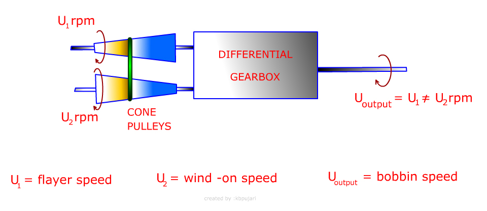 |
Figure 5 : Differential gearbox mechanism
|
|
Figure 5 represents speed of flyer and wind-on speed with differential gear box. Over the cone pulleys belts are shifted, due to which differential speed is obtained from differential gear box as U output = U1≠ U2 rpm. |
|
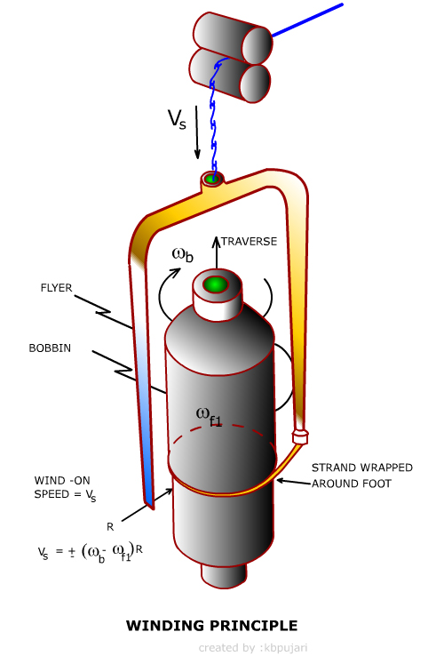
Figure 6 : Principle of winding on roving bobbin
|
|
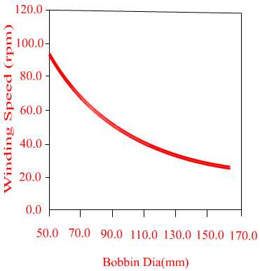
Winding Speed profile |
Let us take the following parameters and calculate the winding speed for different bobbin diameters and plot it. |
| Bare bobbin dia=50mm |
Spindle speed=1000 rpm |
| Roving =1.2 mm |
TPI =1.68 |
| Delivery = 15 m.min |
|
|
|
Figure 7 : Effect of bobbin diameter on winding speed
|
|
Figure 7 represents relationship between winding speed and bobbin diameter. As the diameter of the package increases, winding speed is decreases to maintain the same same winding rate.
|
| |
| Sources : |
-
W. Klein, “Technology of Short Staple Spinning”, The Textile Institute, Manual of Textile Technology, All volumes.
-
Carl A. Lawrence , “ Fundamentals of Spun Yarn Technology”, CRC Publications, 2003.
-
P.R. Lord, Hand Book of Yarn Production : Science, Technology and Economics, Tailor and Francis, 2003.
-
Eric Oxtoby, “Spun Yarn Technology”, Butterworths, 1987.
-
NCUTE publications on Yarn Manufacturing, Indian Institute of Technology, Delhi.
|
|
| |